|
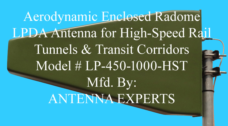
Train Tunnels Aerodynamic Radome Enclosed LPDA Antenna 450–1000 MHz
The LP-450-1000-HST by Antenna Experts is an industrial, military-grade directional Log-Periodic Dipole Array (LPDA) engineered specifically for mission-critical wireless infrastructure in subterranean bore rail tunnels, underground metro lines, and high-speed rail (HSR) transit corridors. Operating continuously across 450–1000 MHz, it consolidates diverse multi-service railway systems—including TETRA, DMR, GSM-R, and FRMCS (5G rail)—into a unified trackside RF aperture.
As global transit networks transition toward digital automation, the LP-450-1000-HST wideband tunnel antenna provides a future-proof trackside RF infrastructure. By providing continuous passband performance from 450 MHz to 1000 MHz, a single antenna installation supports legacy TETRA voice dispatch and GSM-R train protection, while offering native compatibility for FRMCS, LTE Band 8, and 5G rail carrier aggregation. This consolidated approach significantly lowers trackside hardware footprint, deployment complexity, and lifecycle maintenance costs.
Engineered to eliminate signal degradation in harsh rail environments, the LP-450-1000-HST directional tunnel antenna features 100% circumferential TIG-welded dipoles directly bonded to twin 6063-T6 aluminum boom rails. Unlike conventional trackside antennas that rely on mechanical fasteners prone to loosening under train-induced vibrations, this monolithic construction permanently prevents micro-arcing and contact oxidation. The result is certified low passive intermodulation and long-term RF stability across critical ETCS Level 2 and Level 3 signaling networks. Protected by an aerodynamic, EN 45545-2-compliant low-drag radome, the antenna withstands violent train piston pressure transients (±5 kPa) and delivers a stable, forward 10 dBi peak gain with ultra-low passive intermodulation distortion (≤ -150 dBc PIM3).
Technical Specifications Summary
| Parameter |
Specification |
Engineering Standard / Qualification |
| Operating Frequency |
450 – 1000 MHz |
Continuous ultra-wideband coverage (no field tuning needed) |
| Peak Gain |
10 dBi (Typical) |
Compensates for high-frequency longitudinal path attenuation |
| VSWR |
≤ 2:1 (Typical) |
100% factory swept and calibrated across full operating band |
| Nominal Impedance |
50 Ω |
Standard unbalanced coaxial matching |
| Radiation Pattern |
Directional, End-Fire |
Focuses energy strictly down the tunnel bore axis |
| Horizontal Beamwidth (-3 dB) |
65° Typical |
Covers track curves, turnouts, and rolling stock roof antennas |
| Vertical Beamwidth (-3 dB) |
55° Typical |
Minimizes multi-path scatter off tunnel roofs and track ballast |
| Front-to-Back (F/B) Ratio |
≥ 30 dB Typical |
Prevents co-channel oscillation in bi-directional repeater setups |
| Cross-Polar Discrimination (XPD) |
≥ 25 dB (On Bore Axis) |
Reduces multi-path cross-coupling in confined bore waveguides |
| Power Handling Capacity |
250 W CW (1.1 kW Option) |
Continuous average power rated at +55°C ambient |
| Passive Intermodulation (PIM3) |
≤ -150 dBc |
Tested with 2 × 20 W (+43 dBm) RF carriers |
| RF Input Termination |
N-Female (7/16 DIN Optional) |
Silver-plated brass housing with gold-plated beryllium copper pin |
| Surge & Static Dissipation |
Direct DC Ground (≤ 0.05 Ω) |
Continuous grounding through chassis and mounting hardware |
| Radome Ingress Protection |
IP67 (IEC 60529) |
Dust-tight and continuous water immersion protected |
| Operating Temperature |
-40°C to +70°C |
MIL-STD-810G (Methods 501.7 & 502.7, Procedures I & II) |
| Vibration & Mechanical Shock |
IEC 61373 & MIL-STD-810G |
Cat 1 Class B transit vibration; 40g saw-tooth shock (Method 516.6) |
| Aerodynamic Drag & Piston Load |
±5 kPa Differential |
>106 cyclic buffeting reversals; aerodynamic drag Cd < 0.35 |
| Fire, Smoke & Toxicity Rating |
EN 45545-2 (HL1 / HL2 / HL3) |
Non-toxic, halogen-free composite resin matrix |
| Array & Dipole Construction |
100% Fully TIG-Welded |
Solid 12.7 mm 6063-T6 aluminum rods into 19 mm twin boom rails |
| Dimensions & Weight |
650 × 380 × 127 mm; 4.5 kg |
Compact aerodynamic wedge minimizes dynamic wall anchor fatigue |
Multi-Service Spectrum Allocation 450–1000 MHz
As global transit networks transition toward digital automation, the LP-450-1000-HST wideband tunnel antenna provides a future-proof trackside RF infrastructure. By providing continuous passband performance from 450 MHz to 1000 MHz, a single antenna installation supports legacy TETRA voice dispatch and GSM-R train protection, while offering native compatibility for FRMCS, LTE Band 8, and 5G rail carrier aggregation. This consolidated approach significantly lowers trackside hardware footprint, deployment complexity, and lifecycle maintenance costs. The continuous 450–1000 MHz operational band eliminates multi-antenna clutter along trackside tunnel infrastructure by consolidating legacy networks, current standard systems, and next-generation rail wireless protocols over a singular transmission line:
-
450 – 470 MHz (TETRA / DMR / LTE B31 & B72): Mission-critical push-to-talk (PTT) emergency voice communications, yard and shunting operations, tunnel maintenance crews, trackside remote SCADA, and low-band railway carrier telemetry.
-
698 – 862 MHz (FRMCS / 3GPP Band 28 & Band 20): Future Railway Mobile Communication System (FRMCS) 5G broadband connectivity, digital train commands, and automated train control telemetry backhaul.
-
873 – 960 MHz (GSM-R, E-GSM-R, UIC Band, LTE Band 8): ETCS Level 2 / Level 3 European Train Control System, Automatic Train Protection (ATP), real-time rolling stock CCTV backhaul, and carrier aggregation operations.
Core Engineering & Structural Architecture
1. 100% Circumferential TIG-Welded Dipoles
Standard commercial trackside LPDA antennas often employ mechanical clamps, compression rivets, or screw fasteners that inevitably loosen under severe low-frequency acoustic buffeting and cyclic train vibrations. Loose hardware leads to microscopic metal oxide formation, micro-sparking, severe return loss degradation, and severe Passive Intermodulation (PIM) spikes.
The LP-450-1000-HST completely resolves this vulnerability: every single solid 12.7 mm (0.5 inch) 6063-T6 aluminum element is mechanically seated into CNC-machined pockets on dual 19 mm square booms and fully circumferential TIG-welded. This monolithic, all-welded metallic frame guarantees total immunity to vibration fatigue, exceptional structural rigidity, and certified PIM performance (≤ -150 dBc) over decades of rail operations.
2. Balanced Twin-Boom Feed & Integrated Balun
The twin parallel 6063-T6 square extrusions serve simultaneously as primary structural beams and as a balanced two-conductor TEM transmission line. Dipoles alternate from opposite booms, introducing an intrinsic 180° phase inversion that eliminates the need for fragile external jumper wires. The low-loss RF feed coax is routed internally within one hollow boom rail; at the apex, the coaxial shield is bonded directly to Boom 1 while the center conductor bridges to Boom 2, forming an environmentally sealed and mechanically protected RF balun.
3. Subterranean Multimode Waveguide Control
Subterranean transit tunnels act as complex, lossy multimode waveguides where multi-path scatter can cripple high-speed telemetry. The LP-450-1000-HST rail tunnel LPDA antenna solves this with an optimized 55° vertical beamwidth that directs RF energy along the track horizon, avoiding reflections off tunnel ceilings and track ballast. With a complementary 65° horizontal beamwidth and a high $\ge 30\text{ dB}$ front-to-back ratio, it provides robust cell spans of up to 2.5 km between repeater nodes without co-channel feedback or interference. Subterranean railway tunnels behave as lossy, oversized electromagnetic waveguides. The radiation geometry of the LP-450-1000-HST is optimized to handle this environment:
-
Vertical Beamwidth (55°): Concentrates RF energy along the track horizon, avoiding destructive multipath scatter and signal phase cancellation caused by reflections off tunnel ceiling structures and track ballast.
-
Horizontal Beamwidth (65°): Delivers balanced coverage across curved rail alignments, crossover junctions, and passing train roof antennas.
-
Front-to-Back Ratio (≥ 30 dB): Deep back-lobe suppression prevents acoustic self-oscillation and RF feedback loops in bidirectional repeater and bi-cell arrangements.
Tunnel Aerodynamics & Environmental Hardening
Built to survive the violent aerodynamic forces generated by high-speed trains, the LP-450-1000-HST railway antenna utilizes a low-drag wedge radome. Tested to withstand over 106 cyclic piston pressure, it reduces dynamic shear stress on tunnel wall mountings by more than 45%. The fiberglass-reinforced polymer (FRP) radome is fully compliant with EN 45545-2 (HL1–HL3) fire safety standards and IP67 dust/water ingress protection, ensuring complete reliability against brake dust, soot, and pressure washing.
High-speed trains act as pneumatic pistons inside confined tunnels, generating sudden micro-pressure wavefronts and cyclic positive/negative air pressure differentials upon passage.
-
Hydrodynamic Wedge Profile: The aerodynamic tapered profile lowers the frontal drag coefficient to Cd < 0.35, cutting dynamic shear stress on tunnel wall mounting bolts by >45% compared to conventional flat or rectangular antenna housings.
-
Cyclic Piston Buffeting Resistance: Fully qualified and stress-tested to endure over 106 pressure reversal cycles at ±5 kPa at high operational train speeds.
-
Vacuum-Infused Composite Radome: Manufactured using resin transfer molded (RTM) fiberglass-reinforced polymer (FRP) with low-loss vinyl ester resin (εr ≈ 3.2, tanδ < 0.008), keeping RF insertion loss below 0.25 dB. The radome complies with the strictest EN 45545-2 (HL1–HL3) standards for fire safety, low smoke emission, and toxicity.
-
Hermetic IP67 Gasket with Sintered Equalizer: Fluorosilicone perimeter gaskets seal the interior against wash-down detergents, diesel exhaust, and conductive iron brake dust. A bottom-facing sintered porous PTFE breather equalizes barometric pressure transients during rapid train piston events while preventing moisture penetration.
Architectural Comparison: Tunnel RF Distribution
| Metric / Parameter |
LP-450-1000-HST (Discrete Cell) |
Standard Commercial LPDA |
Radiating Leaky Feeder Cable (LCX) |
| Element Junctions |
100% Fully TIG Welded |
Riveted / bolted (vibration-prone) |
N/A (continuous cable line) |
| Forward Directivity |
10 dBi (True Forward Gain) |
7 – 8 dBi |
Negative coupling loss (-65 to -75 dB) |
| Coverage Reach |
1.5 km to 2.5 km per node |
0.8 km to 1.2 km per node |
Continuous line; needs repeaters every 500 m |
| Piston Differential |
±5 kPa certified (>106 cycles) |
Prone to element bending and fatigue |
Cable sagging, hanger clip fatigue |
| Frequency Range |
450 – 1000 MHz (Seamless) |
Narrow / split bands |
High longitudinal loss above 800 MHz |
| Fire & Life Safety |
EN 45545-2 (HL1–HL3 Compliant) |
General commercial plastic (ABS/PVC) |
Variable fire-retardant outer jackets |
| Direct Grounding |
Integrated (≤ 0.05 Ω DC path) |
External arrestor needed |
Requires periodic shield grounding points |
| Maintenance Need |
Virtually Zero (Solid-State Frame) |
Moderate (bolt checks, retightening) |
High (clip replacements, physical damage) |
Frequently Asked Questions
Which antenna is best suitable for high speed train or rail tunnels communication?
The Antenna Experts LP-450-1000-HST is highly suitable for train tunnels communication because it is a military-grade, high-performance directional Log-Periodic Dipole Array (LPDA) engineered specifically for mission-critical railway and subway communications. Covering a continuous ultra-wideband spectrum of 450–1000 MHz, this rail-grade tunnel antenna seamlessly integrates TETRA, DMR, GSM-R, and FRMCS (5G rail) into a single ruggedized enclosure. Designed to replace lossy radiating leaky cables (LCX), it delivers a stable 10 dBi gain, an aerodynamic wedge radome, and extreme durability against subterranean piston shockwaves.
Why use a directional LPDA instead of radiating leaky feeder cable (LCX) in rail tunnels?
Radiating leaky feeder cable (LCX) exhibits high longitudinal RF attenuation at frequencies above 800 MHz (such as GSM-R, LTE Band 8, and FRMCS). It also requires continuous physical mounting along the entire tunnel bore, leaving it exposed to hanger displacement, physical damage, and mechanical fatigue from train wind buffeting. The LP-450-1000-HST discrete-cell architecture uses a concentrated 10 dBi forward beam to project RF energy over 1.5 to 2.5 km between repeater sites, reducing installation costs and in-tunnel maintenance overhead.
How does the antenna prevent Passive Intermodulation (PIM) interference?
Rail corridors experience continuous, high-amplitude vibrations. In standard antennas with bolted or riveted joints, this motion causes microscopic shifts, contact oxidation, and micro-sparking—the root causes of PIM. The LP-450-1000-HST eliminates non-linear metallic contacts by CNC-seating and 100% circumferential TIG-welding every dipole directly to the twin support booms, guaranteeing an intermodulation distortion rating of ≤ -150 dBc.
What mounting and orientation options does the antenna bracket support?
The antenna comes standard with a heavy-duty Grade 304 stainless-steel V-clamp mounting bracket that secures to any trackside or tunnel mast up to 52 mm (2.0 inches) OD. A 90° rotatable bracket flange enables quick site selection between vertical and horizontal polarization while providing independent, positive mechanical locking for azimuth and elevation tilt angles.
|