Instrument Landing Systems (ILS) Antenna
Antenna Experts manufactures various type of Instrument Landing Systems antenna ILS antenna which includes horizontal polarized omni ILS antenna for 106-120MHz band for VOR/DVOR application, 3 elements horizontal polarized ILS yagi antenna, 5 elements horizontal polarized ILS yagi antenna, ILS horizontal polarized directional glide slope antenna from 328-336MHz band for monitoring the signal of a localizer array used in air navigation instrument landing systems.
Antenna Experts manufactures a fully compliant ground based Instrument Landing Systems Antennas ILS antenna for the Aviation Industry. Our ILS antenna systems first of all, is works highly directive manner in which signals are radiated to approaching aircraft with exceptional reliability. All of our ILS Antennas produce asymmetrically shaped and steered patterns to provide safer, smoother and more precise landings at airports wherever they are installed.
Antenna Experts ILS antenna is used to land an aircraft when visibility is poor. This radio navigation system guides the aircraft down a slope to the touch down area on the runway. Multiple radio transmissions can be used that enable an exact approach to landing with an Instrument Landing Systems (ILS) antenna. A localizer is one of the radio transmissions. Instrument Landing Systems Antenna is used to provide horizontal guidance to the center line of the runway. A separate glideslope broadcast provides vertical guidance of the aircraft down the proper slope to the touch down point. Compass locator transmissions for outer and middle approach marker beacons aid the pilot in intercepting the approach navigational aid system. Marker beacons provide distance from the-runway information. Together, all of these radio signals make an ILS a very accurate and reliable means for landing aircraft.
| 1. | ILS-108-118-L | 108-118MHz | H Omni | 3dBi | 108-118MHz | 2:1 | Omni | Linear H | 360 Degrees | 70 Degrees | 50 Ohms | Fiberglass | N-Female |
| 2. | ILSY-108-118-7 | 108-118MHz | Yagi | 7 dBi | 108-118MHz | 2:1 | Directional | Horizontal | 110 Degrees | 65 Degrees | 50 Ohms | N/A | N-Female |
| 3. | ILSY-108-118-10 | 108-118MHz | Yagi | 10 dBi | 108-118MHz | 2:1 | Directional | Horizontal |
70 Degrees | 55 Degrees | 50 Ohms | N/A | N-Female |
| 4. | GS-328-336-10 | 328-336MHz. | Corner Ref | 10dBi | 328-336MHz | 1.5:1 | Directional | Linear H | 23 Degrees | 80 Degrees | 50 Ohms | N/A | N-Female |
| 5. | ADSY-1060-12 | 1030-1090MHz. | Yagi | 12dBi | 1030-1090MHz | 1.5:1 | Directional | Linear Vertical | 55 Degrees | 45 Degrees | 50 Ohms | Fiberglass | N-Female |
| 6. | DME-960-1240-6 | 960-1240MHz. | Vertical Omni | 6 dBi | 960-1240MHz | 2:1 | Omni | Linear Vertical | 360 Degrees | 38 Degrees | 50 Ohms | Fiberglass | N-Female |
| 7. | DME-960-1240-9 | 960-1240MHz. | Vertical Omni | 9 dBi | 960-1240MHz | 2:1 | Omni | Linear Vertical | 360 Degrees | 18 Degrees | 50 Ohms | Fiberglass | N-Female |
| 8. | DME-960-1240-12 | 960-1240MHz. | Vertical Omni | 12 dBi | 960-1240MHz | 2:1 | Omni | Linear Vertical | 360 Degrees | 9 Degrees | 50 Ohms | Fiberglass | N-Female |
| 9. | DME-1100-8-180 | 960-1240MHz. | Offset Omni | 8 dBi | 960-1240MHz | 2:1 | Directional | Directional | 180 Degrees | 38 Degrees | 50 Ohms | Fiberglass | N-Female |
| 10. | DME-1100-11-180 | 960-1240MHz. | Offset Omni | 11 dBi | 960-1240MHz | 2:1 | Directional | Directional | 180 Degrees | 18 Degrees | 50 Ohms | Fiberglass | N-Female |
| 11. | DME-1100-14-180 | 960-1240MHz. | Offset Omni | 14 dBi | 960-1240MHz | 2:1 | Directional | Directional | 180 Degrees | 9 Degrees | 50 Ohms | Fiberglass | N-Female |
| 12. | AY-128 | 117-137MHz. | Yagi | 11 dBi | 117-137MHz | 2:1 | Directional | V or H | 60 Degrees | 50 Degrees | 50 Ohms | N/A | N-Female |
| 13. | AQY-128 | 117-137MHz. | Yagi | 17 dBi | 117-137MHz | 2:1 | Directional | V or H | 30 Degrees | 30 Degrees | 50 Ohms | N/A | N-Female |
| 14. | AC-118-137 | 118-137MHz. | Omni | 2 dBi | 118-137MHz | 2:1 | Omni | Vertical | 360 Degrees | 78 Degrees | 50 Ohms | Fiberglass | N-Female |
| 15. | CD-100-156 | 100-156MHz. | Omni | 2 dBi | 100-156MHz | 2:1 | Omni | Vertical | 360 Degrees | 78 Degrees | 50 Ohms | Fiberglass | N-Female |
| 16. | ACHP-118-400 | 118-400MHz. | Omni | 2 dBi | 118-400MHz | 2:1 | Omni | Vertical | 360 Degrees | 78 Degrees | 50 Ohms | Fiberglass | N-Female |
| 17. | LP-108-470 | 108-470MHz. | LPDA | 11 dBi | 108-470MHz | 2:1 | Omni | V or H | 65 Degrees | 55 Degrees | 50 Ohms | N/A | N-Female |
| 18. | LP-225-400 | 225-400MHz. | LPDA | 11 dBi | 225-400MHz | 2:1 | Omni | V or H | 65 Degrees | 55 Degrees | 50 Ohms | N/A | N-Female |
Please contact us for detailed datasheet in PDF format including image, VSWR curve & radiation patterns.
Precision Radio Navigation and ILS Antenna System Architecture
Instrument Landing Systems (ILS) are mission-critical ground-based installations designed to facilitate safe aircraft arrivals, particularly during periods of low visibility. The system operates by radiating highly directive, asymmetrically shaped radio signals that define a precise three-dimensional path to the runway touchdown zone. This navigation suite is composed of three primary components: the Localizer, which utilizes horizontally polarized antennas to provide lateral guidance relative to the runway centerline; the Glide Slope (GS), which offers vertical guidance along a predetermined descent angle; and Marker Beacons, which provide discrete distance-from-threshold information. By integrating these transmissions, Antenna Experts ILS solutions ensure aircraft are steered with exceptional reliability and precision during the final approach phase.
Glide Slope Technology and Vertical Path Precision with ILS Antenna
The GS-328-336-10 Glide Slope antenna is a specialized horizontal polarized array engineered to provide vertical guidance under Instrument Flight Rules (IFR). This system utilizes a series of collinear dipoles positioned in front of a corner reflector to generate highly controlled horizontal and vertical radiation patterns. To maintain signal integrity in fluctuating climates, the RF distribution and integral monitor systems are constructed using low-loss, phase-stable semi-rigid coaxial cables. This robust design minimizes sensitivity to environmental shifts, allowing for an increased flow of air traffic near the Glide Path (GP) tower. The entire assembly is encased in a fiberglass radome and finished in international orange, rated to withstand wind speeds of 200 Km/Hr and temperatures ranging from -40°C to +70°C.
Horizontal Guidance and VOR/DVOR Omnidirectional ILS Antenna Solutions
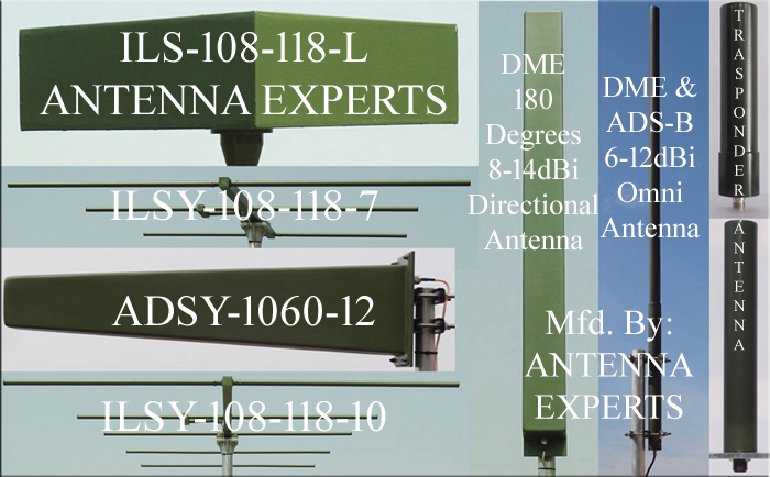
For horizontal navigation and center-line guidance, the ILS-108-118-L represents a high-reliability, horizontally polarized omni-directional dipole antenna. Ideally suited for VOR (VHF Omnidirectional Range) and DVOR applications, this antenna utilizes 6063T6 military-grade aluminum alloy and is hermetically sealed within an ABS radome. Its design focuses on maintaining a minimal VSWR through advanced internal impedance matching, ensuring that signal reflection is minimized for ground-to-air communication. The wide vertical beam-width of these ILS antennas facilitates clear links across diverse altitudes, while the MIL-STD-810G compliant powder coating provides a formidable defense against salt spray, acid rain, and UV degradation in both coastal and desert environments.
High-Gain ILS Yagi Antenna and Directional Efficiency
The ILSY series of Yagi antennas, including the 3-element ILSY-108-118-7 (7 dBi) and the 5-element ILSY-108-118-10 (10 dBi), are designed for directional ILS applications requiring specific sector coverage. These antennas feature a unique feed mechanism that eliminates the need for a traditional folded dipole, instead using a specialized matching device to optimize efficiency and maintain a low VSWR across the 108–118 MHz band. Supplied factory-tuned to avoid the need for complex field adjustments, these horizontal polarized arrays provide the high directivity necessary for accurate air navigation instrument systems. Their rugged construction and N-Female terminations ensure they remain stable under the mechanical stress of high-wind airport environments.
Distance Measuring Equipment (DME) and Broadband ILS Support
Complementing the ILS suite, Antenna Experts manufactures a comprehensive range of Distance Measuring Equipment (DME) antennas covering the 960–1240 MHz band. These systems are available in both omni-directional configurations (with gains of 6, 9, and 12 dBi) and directional configurations (offering 8, 11, and 14 dBi with 180-degree horizontal beam-widths). DME antennas are essential for providing aircraft with accurate slant-range distance to the ground station. For broader tactical requirements, Antenna Experts also produces wideband antennas covering the entire 100–400 MHz VHF/UHF aeronautical band, ensuring that airport authorities have access to the highest-performance directional and omni-directional solutions in the industry.
Wide Vertical Beamwidth of ILS Antenna
The wide vertical beam-width of high power Instrument Landing Systems ILS antennas allows clear communication for ground, sea, and ground-to-air applications. The powder coating on all metallic surfaces ensures complete protection from the corrosive gases, ultraviolet radiation, salt spray, acid rain present in coastal areas and sand storm environmental in dessert area. The Instrument Landing Systems (ILS) antenna is designed as per MIL-STD-810G standards.


 certified company manufactures Antennas System for SIGINT, EW, UAV, SCADA, TETRA, CNI, ATC, SATCOM, DME, RCIED Jamming, Surveillance, Broadcast, Radio Relay, Energy, Oil Field, Smart Grid and Agriculture applications")
 certified company manufactures Antennas System for SIGINT, EW, UAV, SCADA, TETRA, CNI, ATC, SATCOM, DME, RCIED Jamming, Surveillance, Broadcast, Radio Relay, Energy, Oil Field, Smart Grid and Agriculture applications")